
All equipment should be returned to our manufacturing partner; Cambertronics. Their address is: QMI Repair Manager, Quality Monitoring Instruments Ltd, c/o Cambertronics Ltd, Unit 12, Manfield Park, Guildford Road, Cranleigh, Surrey GU6 8PT.
The returned equipment MUST have a Manifest/Packing Note stating shipping contents along with details about who to contact to arrange Purchase Order and Shipping Instructions.
The above documentation should be emailed to QMI in London; qmi@oilmist.com
The process for changing Settings on a QMI Monitor is clearly described in all QMI Manuals. The principle is the same regardless of whether the Monitor is a TRIPLEX™ or MULTIPLEX™.
For reference the process is detailed in Section 6.2 on page 43 of the Manual for MULTIPLEX™ Atmospheric Systems.
Please see the appropriate section of the Installation Manual relevant to your system. The topic is covered under the Section Setting Up The System.
The process for setting Alarm Levels for a QMI system is clearly described in all QMI Manuals. The principle is the same regardless of whether the Monitor is a TRIPLEX™ or MULTIPLEX™.
For reference the process is detailed in Section 6.2 on page 43 of the Manual for MULTIPLEX™ Atmospheric Systems.
A ‘Fault Directory’ can be found on the face plates of both QMI Monitors. This describes the Alarms encountered relevant to the Readings.
More detailed information can also be found in the Installation Manuals relevant to your system.
Yes, the current Monitor keys are Lorilin Brand (Part No Q0103L) with earlier keys being the TOK brand, Part No. Q0103.
Yes, the Part No is Q0109. Please also see the Product Catalogue for visual reference.
The process for cleaning lenses on a Q02 Engine Detector is described in detail in the Engine Manual.
It is possible to isolate a Q02 Engine Detector from the system if it is faulty, whether it is on a MULTIPLEX™ or TRIPLEX™ system.
It is the same process to follow for isolating regardless of which Monitor you have, please refer to the MULTIPLEX™ ENGINE Manual for instructions.
We would strongly urge you to keep a back-up Q02 Detector Head as a spare should this situation occur and in order to ensure your systems continuous operation.
The process for cleaning lenses is described in detail in the Atmospheric Manuals.
We would refer you to section 7.2 on pages 55-56 of the MULTIPLEX™ Manual for instructions. A video describing the process can also be found here.
No. These units are factory-set and must be returned to QMI for re-calibration.
The Lenses (and the Optics and Collimators) can be replaced on our Detectors, however as they must be re-calibrated after replacement the unit(s) have to be returned to QMI for repair.
PLEASE NOTE: It is NOT possible for end users to change these items and any attempt to do so will invalidate the Warranty.
It is possible to isolate an Atmospheric Sensor from the system if it is faulty, whether it is on a MULTIPLEX™ or TRIPLEX™ system. It is the same process to follow for isolating regardless of which Monitor you have and the process can be found in Section 5.3 on page 38 of the MULTIPLEX™ Manual. There is also a video describing the process which can be found here.
We would strongly urge you to keep a back-up Q10 Sensor as a spare should this situation occur and in order to ensure your systems continuous operation.
Many different replacement parts are available for the Q02 Detector Head, including Gaskets and Filters.
Please refer to the Product Catalogue for a visual reference and Part No.
Yes, replacements Fans are available for Atmospheric Sensors for Serial Nos. A1383 onwards. The Part No. is Q1004, and the Fan comes with replacement fixing screws and washers.
Yes, we can provide a replacement PCB Power Supply for MULTIPLEX™ Monitors with Serial Nos. 703 onwards. The Part No. is Q0106.
Serial numbers for both the TRIPLEX™ and MULTIPLEX™ Monitors can be found on the front face panels. They are on the bottom left hand corner for MULTIPLEX™ (prefixed with an ‘M’) and in the middle on the right hand side for TRIPLEX™ (prefixed with a ‘T’).
The Serial number for an Atmospheric Sensor can be found on a label affixed on the front of the Sensor, on the left hand side just behind the front grill.
These numbers are stamped along the outer edge of the Back Plate of the Detector Head. Sometimes they are obscured by dirt but they can be found ‘punched’ into the metalwork.
Yes, but depending on how the existing system has been installed.
In some instances we have found that the oil mist extraction points for an Engine system have been installed too low in the crankcase of the engine – sometimes even level with the oil in the sump of the engine. (As shown below.)
This would naturally make the sensor ineffective.
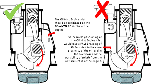
In other cases we have found that the extraction point has been installed adjacent to the upward stroke of a piston. In this event, the piston ‘drags’ oil upwards towards the sensor extraction point, (as shown in the illustration below,) in which case the Oil Mist reading would be inaccurate.
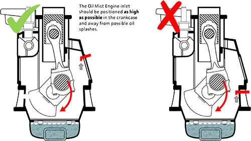
In both these cases though, it is possible to re-position the extraction point in the crankcase following which the QMI Oil Mist Detector would work, (using the existing pipework.)
There are two types of fan on an Engine system; VBM5 and VBM3. The difference can be identified by looking at the Inlet and Outlet couplings: VBM5 has two identical 38mm (1.5” BSP) couplings on the Inlet and Outlet VBM3 has non-identical couplings. The Inlet is 25mm (1” BSP) and the Outlet is 19mm (¾” BSP)
Currently our Atmospheric Sensors are not ATex approved as they require an internal 12 Volt Fan to draw air into and through the sensing chamber. We are looking into using other means of inducting the air through the chamber but do not have a ATex option at this time.
In some installations though it would be possible to mount the Sensors at the exhaust end of the ventilation duct, (i.e. in a non ATex zone,) in which case the Sensors would still pick up the mist.
In this example, the crucial factor would be what the length of the exhaust duct would be and the period of the time the mist took to pass through that length of duct.
QMI Multiplex Monitors use Harting Connectors for power and signalling purposes, as shown by the illustration below on the left.

There should be no problem in re-activating QMI equipment, and Installation and Maintenance Manuals are available for all our systems. Pre-start-up it would be advisable to follow some basic processes:
The QMI Oil Mist Detection System works on the principle of light scatter so every channel should read an oil mist reading when the engine is running.
This might only be a very low level on certain engines so the alarm limits should be set fairly low to start with. However, if the channel is reading zero with the engine running there is a problem.
Additional support is available if the system fails to start. In this instance, the SERIAL numbers of the MONITOR and DETECTORS along with the VESSEL name and IMO number would help us to assist with your systems operation.
This depends on whether your system is monitoring Oil Mist in the Engine Crankcase or a Machine Room Atmosphere.
Spare parts are available to remedy this problem. Contact QMI or your local country QMI Agent, (addresses on the website at www.oilmist.com) where they may hold spare parts stock.
Additional support is available if this problem persists, in which case the SERIAL numbers of the MONITOR and DETECTORS along with the VESSEL name and IMO number would help us to assist with your systems operation.